Efficient Mucking Loader
1. Intelligent integration operations
2. Quick outfit change
3. Multi-model adaptation, expert in small space operations
4.A variety of models are available, with customized sizes supported.
Product Details
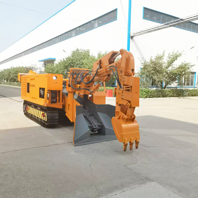
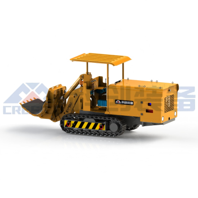
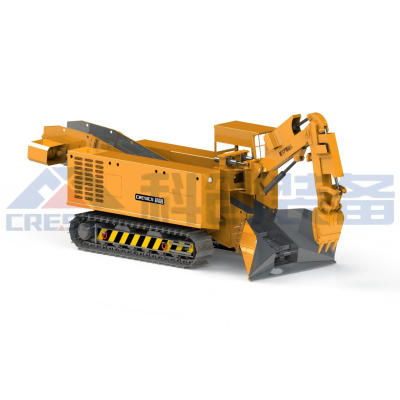
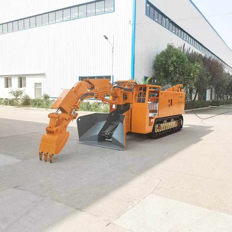
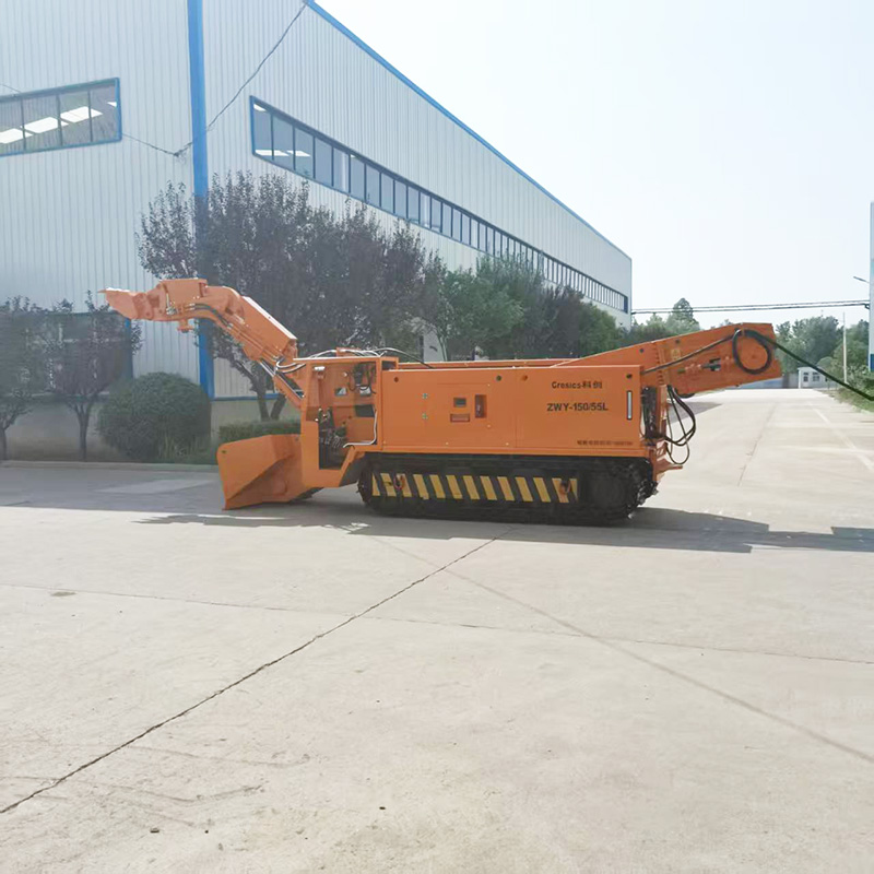
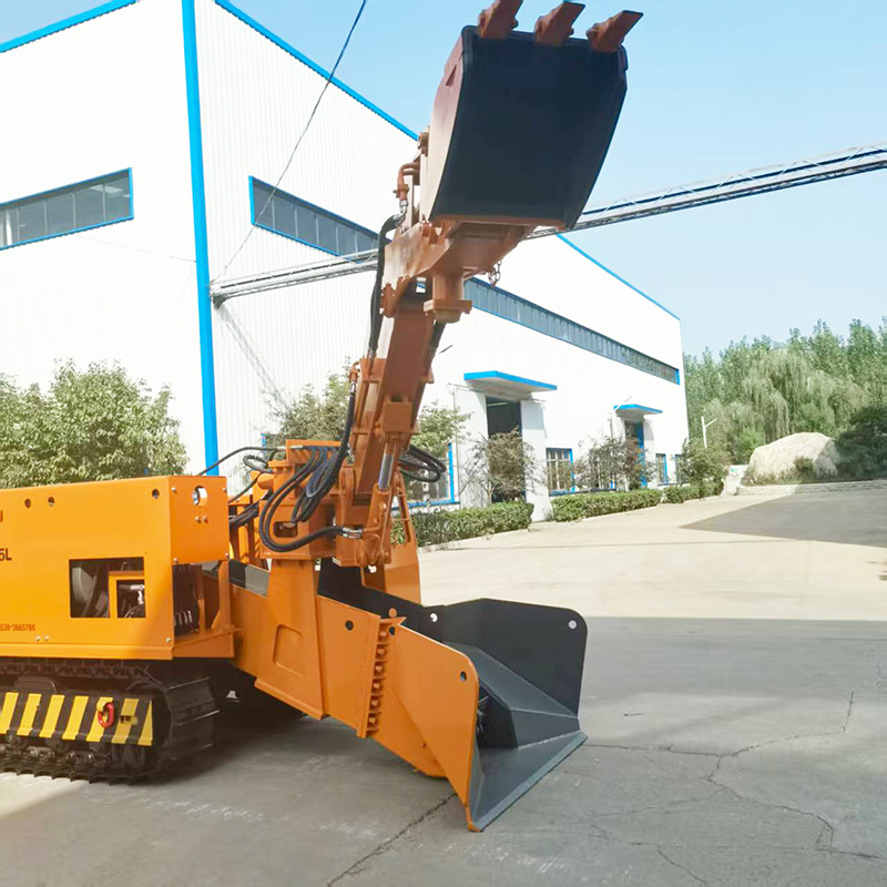
The Efficient Mucking Loader is mainly composed of the boom system, conveyor trough mechanism, crawler travel assembly, hydraulic system, and electrical system.
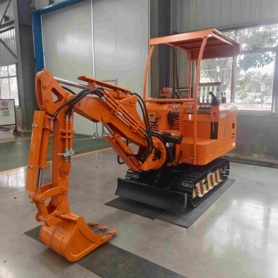
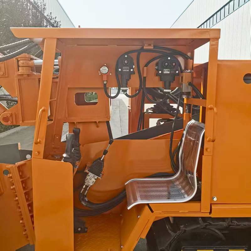
1.Operator Cab:
The cab of the Efficient Mucking Loader features an ergonomic design and is equipped with a protective canopy for effective falling object prevention. All operation instrument panels are rationally laid out with clear display, which dual enhances operational convenience and working safety.
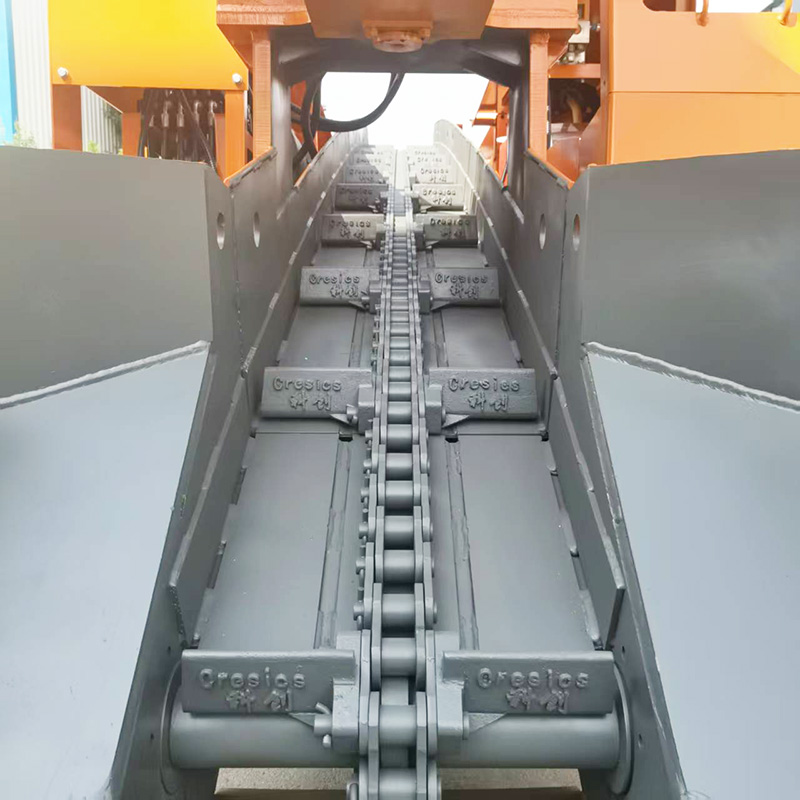
2.Scraper Conveyor:
The scraper conveyor trough is the conveying component of the excavator, which is responsible for transporting ores, mineral materials, sludge, and earth and rock loaded into the trough by the boom to underground conveying equipment such as belt conveyors and mining cars. It consists of a conveyor trough, a scraper assembly, a driven sprocket, a driving sprocket, a slag conveying motor, a chain and other components. Controlling the extension and retraction of the trough lifting oil cylinder enables the lifting and lowering of the conveyor trough to meet the requirements of working or traveling respectively.
3.Travel Mechanism:
This machine adopts the standard combined crawler of hydraulic excavators directly. The crawler wheels are made of high-strength alloy steel, featuring high structural strength and excellent wear resistance, and can adapt to various complex working conditions such as muddy, soft and wet ground. The two crawlers are driven by two separate hydraulic motors respectively, which are mounted at the rear of the crawler frame for easy maintenance and servicing.

Parameters
Item | ZWY-80/30L | ZWY-80/37L | ZWY-80/45L | ZWY-100/45L | ZWY-120/65L | ZWY-150/55L | ZWY-180/75L | ZWY-220/75L | |
Main Technical Parameters | |||||||||
Applicable Section (Width × Height) m | 3.2×2.2 | 3.5×2.5 | 4×2.5 | 4.8×3.2 | 5.4×4.0 | 5.8×4.5 | 6.2×5 | 7.5×5.5 | |
Applicable Axis Width* | (-16° ~ +16°) | (-20° ~ +20°) | ( -32° ~ +32°) | ||||||
Loading Capacity m³/h | 80 | 100 | 120 | 150 | 180 | 220 | |||
Control Mode | Hydraulic Pilot Control | ||||||||
Main Motor Power KW | 30 | 37 | 45 | 55 | 75 | ||||
Digging Width mm | 3200 | 3500 | 4000 | 4600 | 5400 | 5800 | 6200 | 7000 | |
Digging Distance mm | 1500 | 1600 | 1800 | 2150 | 2500 | 3300 | |||
Digging Height mm | 1800 | 2200 | 3000 | 3500 | 3800 | 4000 | 4300 | ||
Digging Depth mm | 400 | 500 | 800 | 990 | 1050 | ||||
Unloading Height (Adjustable) mm | 1200 | 1450 | 2000 | ||||||
Unloading Distance (Adjustable) mm | 1150 | ||||||||
Max. Rotation Angle* | ±36° | ±45° | ±55° | ||||||
Max. Transport Material Size mm | < φ500 | < φ580 | < φ625 | < φ780 | |||||
Boom Structure | Single Boom | Single Boom (or Double Boom) | Double Boom | ||||||
Hoisting Speed m/min | 44 | ||||||||
Track Gauge (Adjustable) mm | 890 | 890 | 900 | 1110 | 1190 | 1400 | |||
Travel Speed m/s | 0.5 | ||||||||
Ground Clearance mm | 300 | ||||||||
Min. Turning Radius m | ≥ 5 | ≥ 7 | ≥ 8 | ||||||
Ground Pressure MPa | ≤ 0.1 | ||||||||
Rated Working Pressure MPa | 23 | ||||||||
Max. Bucket Size | Length mm | 3350 | 4200 | ||||||
Width mm | 850 | 900 | 1000 | 1100 | 1200 | ||||
Height mm | 1200 | 1400 | 1500 | 1650 | |||||
Max. Bucket Weight Kg | 2300 | 3000 | 3500 | ||||||
Max. Overall Dimensions (Working) | Length mm | 6000 | 6500 | 6800 | 7000 | 7500 | 8800 | ||
Width mm | 1750 | 1800 | 2200 | 2350 | 2640 | ||||
Height mm | 1750 | 1750 | 1800 | 2900 | 3250 | 3600 | 3800 | 4200 | |
Machine Weight Kg | 7600 | 8000 | 8200 | 11200 | 13800 | 15200 | 17800 | 20000 | |
Operating Conditions
1.The Protodyakonov hardness coefficient f of rock is ≤12, the lump size is ≤500 mm, and the loose bulk density is ≤1.8 t/m³.
2.The altitude is ≤1000 m. Special design is required for plateau environments above 1000 m in altitude.
3.The roadway ambient temperature ranges from -5℃ to +40℃, with a maximum relative humidity of ≤90% (at 25℃).
4.The extreme voltage deviation is ±5%, and the extreme AC frequency deviation is ±1%.
5.The roadway gradient is ≤25°. Special design or necessary measures shall be adopted for operation in tunnels with a gradient exceeding 25°.
6.The content of coal dust and methane explosive gas around the loader during operation shall comply with the safe content specified in the Coal Mine Safety Regulations.
Transportation and Storage
1. Factory Lifting and Transportation
The Side Dump Rock Loader is transported by road. The machine can be directly hoisted onto the trailer by a crane or overhead traveling crane. Triangular sleepers shall be placed under the front and rear tires, and the tires of the loader shall be fastened to the appropriate positions of the trailer with ropes. The loader must be placed flat and firmly bound before factory transportation.
2. Lifting and Transportation to Mine Working Face, Underground Installation and Precautions
According to the conditions of the mine mouth, the loader can directly enter the operation site through the inclined shaft; for the vertical shaft, the loader must be disassembled and hoisted into the mine in parts.
3. Storage Requirements
The loader shall be stored in a place equipped with rainproof and sun protection facilities. If stored for more than six months, anti-rust treatment shall be re-conducted.